- SEIKA Digital Image Corporation.
- ProductList
- PIV(Particle Image Velocimetry)
PIV(Particle Image Velocimetry)
What is PIV (Particle Image Velocimetry)

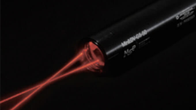
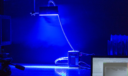
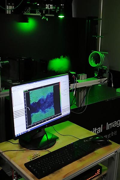
PIV (Particle Image Velocimetry) is a technique for visualizing fluids that enables measurement of velocity distribution within a spatial plane by flowing particles and capturing two or more images of the particles illuminated by a laser sheet. This method enables not only planar but also three-dimensional measurement of instantaneous velocity and direction, and is one of the time-of-flight (TOF) measurement techniques. PIV is widely used in various fields such as fluid dynamics and aerospace engineering to non-invasively measure the velocity field of fluids.
>What is PIV
PIV System Lineup(In Japanese)
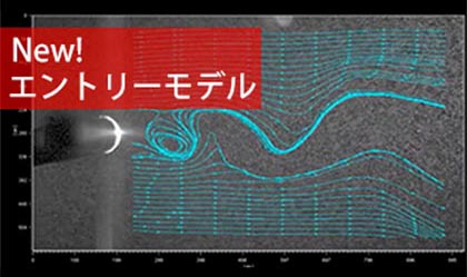
NEW! Entry-Level PIV System
An entry-level PIV system has been introduced for easy setup, with the capability to upgrade through the addition of algorithms or cameras. This system includes software with entry-level specifications, and a special model for Academic is also available.
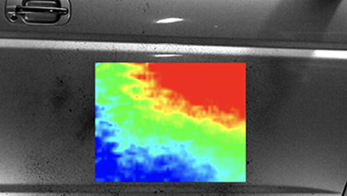
2D-PIV System Measures
A 2D-PIV system measures two-dimensional velocity components within a plane and can handle all velocity ranges, by using frame straddling, and achieves high measurement accuracy through the latest PIV analysis algorithms.
Stereo 3D-PIV System
A stereo 3D-PIV system enables measurement of the three-dimensional velocity components within a Stat Lighti sheet plane, achieving high spatial resolution and easy, high-precision measurements. It is the most practical simultaneous multi-point 3D measurement method.
Time Series PIV
The latest PIV system enables high-speed sampling from several kilohertz to several tens of kilohertz, which was impossible with conventional PIV technology. It is applicable for measuring high-speed flows and large areas.
Micro PIV and Micro LIF Systems
Micro PIV and Micro LIF systems are designed to analyze velocity distribution, mixing, and diffusion in microfluidic systems with small flow rates (microfluidics). They are constructed by combining optical systems such as microscopes and dedicated tracer particles and components for Micro PIV.
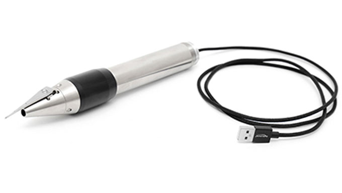
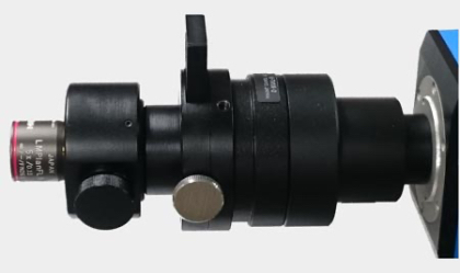
Probe PIV System
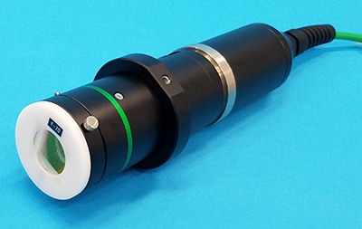
The Probe PIV system is a 3D-PIV system with two cameras installed inside a box, and the laser is also transmitted by fiber, making it an integrated system. ShineFlug's focus, laser sheet, and calibration are not required.
Shadowgraph PIV System
Shadowgraph PIV System is a technique that captures the flow of bubbles using shadowgraphy and analyzes it using PIV to visualize the flow pattern. By capturing images of bubbles or small particles, it is possible to obtain information about the particle size and flow velocity distribution.
LED-PIV System
The LED-PIV system measures the 2D velocity components in the plane illuminated by an LED light sheet. It achieves high-speed and accurate analysis with a standard FFT correlation algorithm. Because the light source is LED, it can be used safely and is optimized for educational purposes.
System Features

- Our company's developed integrated software
The PIV-dedicated control and analysis software ‘Koncerto II’ allows for seamless completion of measurement and analysis within the same software. - High-precision PIV analysis
Adopts the state-of-the-art deformation correlation algorithm developed by the German Aerospace Center (DLR).
Multiple algorithms are available, including Micro PIV and the FD4 algorithm for time-series analysis. - Propose the best solution to meet your needs
We propose the optimal solution that meets your needs, based on our extensive track record from real-scale wind tunnels to micro-scales. We offer various light sources, high-resolution cameras, high-speed cameras, etc. according to the measurement target. - A diverse range of systems
We offer a diverse range of systems including an entry-level model with LED lighting source designed for safety in educational settings, and a Shadowgraph PIV system for bubble flow measurements, among others.
PIV Control and Analysis Software ‘Koncerto II’.

‘Koncerto II’ is an integrated PIV software that combines high-level system control performance and advanced analysis capabilities. It supports a wide range of measurement cameras, lasers, and peripheral equipment, and is designed as a platform for laser measurement and imaging measurements such as PIV and PLIF. The analysis algorithm includes state-of-the-art deformation correlation developed by the German Aerospace Center (DLR), as well as time-series PIV algorithms (FD4 correlation) that can accurately analyze periodicity in time-series PIV data and have temporal interpolation functions, and SAT-PTV, which removes the effect of Brownian motion without time averaging for micro-PIV analysis.
Feature
"A first-of-its-kind fully integrated measurement platform developed in Japan."
- High expandability
Not only PIV, but also excellent expandability in visualization measurement that supports PLIF (combustion measurement). - Compatible with a variety of cameras
Our company has an in-house development structure that enables us to support various types of cameras, including domestic and foreign-made products, high-speed, and high-sensitivity cameras, and we can quickly adapt to new models. - Supports various algorithms to support high-precision measurements
Supporting various algorithms for high-precision measurements, ‘Koncerto II’ features state-of-the-art algorithms developed by the German Aerospace Center (DLR). By optimizing multiple processes, it enables both high precision and high speed processing. It also supports algorithms such as FD4 correlation, a patented technology that complements erroneous vectors for time-series PIV, and SAT-PTV, which considers the impact of Brownian motion for micro-PIV analysis. For more details on each algorithm, please refer here. - Abundant post-processing
Supports POD (Proper Orthogonal Decomposition) for comparison with CFD data, etc. Also compatible with vorticity display. - Equipped with a phase filter for PIV images.
- The automatic analysis function (script function) is available.
- Automatic Δt correction function (optional)
Data Formats
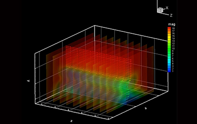
The data format for PIV can be obtained using the same workflow for both 2D-PIV and stereo 3D-PIV. The image below shows a PIV analysis image of a free jet ejected from a nozzle with a 100mm × 100mm square cross-section. The dashed lines on the 2D-PIV data correspond to the measurement plane of the stereo 3D-PIV.
2D2C ( 2 Dimensions 2 Components)
- Velocity evaluation of two components in a two-dimensional cross-section using a 2D-PIV system.
- PIV system can obtain information on the x and y directions which cannot be measured by hot-wire anemometers or pitot tubes.
- The data processing is relatively lightweight, making it ideal for realistic flow visualization.
2D3C ( 2 Dimensions 3 Components)
- The evaluation of three components of velocity in a two-dimensional cross-section can be achieved through the use of a Stereo 3D-PIV system.
- By using multiple cameras, it is possible to obtain flow velocity information in the x, y, and z directions with Stereoscopic 3D-PIV.
- The entire system is optimized, including a dedicated mount that enables focusing throughout the entire field of view, achieving high-precision 3D data acquisition.
Examples of Uses
- Various wind tunnel and water tank experiments.
- Engine and combustor.
- Fans, turbines, and rotating machines.
- Fuel cell stack
- Clean rooms, indoor airflow.
- Spray
- Sports fluids
- Blood flow.
-
Micro TAS
Measurement Example Video
Unsteady 2D-PIV measurement in a boundary layer wind tunnel@Tokyo Polytechnic University
2D-PIV@1,000Hz: Horizontal section of prism model (height 30mm), angle of view 500mm
Karman vortices in the wake of a cylinder (vector) by a time-series 2D-PIV system
Karman vortices (streamlines) in the wake of a cylinder by a time-series 2D-PIV system
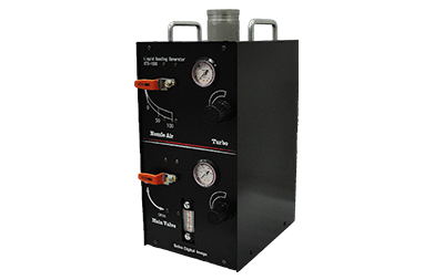
Efficient wind tunnel experiments using original seeding equipment
Measurement example archive
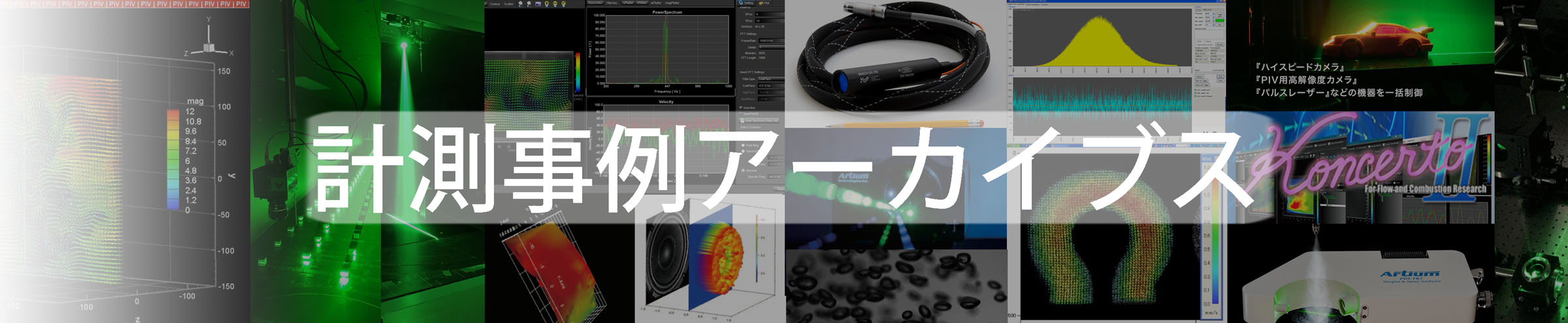
In the measurement case archives, we will introduce the PIV measurement cases that were introduced on the Seika Digital Image website in the past. Please note that some of these pages are available in Japanese only.
System Configuration List - We have various equipment used in PIV
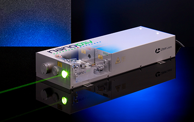
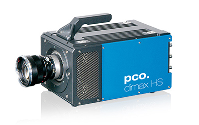
In addition to software that collectively controls PIV analysis and various optical equipment used in PIV such as laser sheet optical system, cylindrical lens, 90 degree mirror block, optical fiber optical system, light arm, etc. We have a variety of equipment such as high-speed cameras, high-resolution cameras, next-generation seeding systems and laser light sources.
Some product detail pages linked below are available in Japanese only.
Major Deliveries

2For more than 20 years, we have delivered more than 300 systems to the research and development departments of national and public universities and companies. Utilizing our many years of know-how, we will propose the optimal system for your needs. In addition to PIV, LIF (combustion measurement) is also possible with a similar setup system.
National and Public Universities
横スクロールでご覧いただけます。
| Muroran Institute of Technology: 2D-PIV software | Hirosaki University: 2D-PIV system | Akita Prefectural University: 2D-PIV software | Yamagata University: Time series 2D-PIV system |
| Yamagata University: Confocal Micro PIV System | Tohoku University: 2D-PIV system (many installed) |
Tohoku University: 2D-PIV software (many installed) |
Tohoku University: Confocal micro PIV system (multiple installations) |
| Japan Advanced Institute of Science and Technology: Confocal Micro PIV System | Kanazawa University: 3D-PIV system | Kanazawa University: 2D-PIV system | University of Tsukuba: 3D-PIV software |
| Chiba University: Time series 3D-PIV system | Chiba University: Confocal Micro PIV System | University of Tokyo: Time series 2D-PIV system | University of Tokyo: 2D-PIV software |
| University of Tokyo: Confocal Micro PIV System | Tokyo Institute of Technology: Time-series 3D-PIV system | Tokyo University of Agriculture and Technology: 2D-PIV system | Tokyo University of Agriculture and Technology: Time Series 3D-PIV System |
| Osaka University: Confocal Micro PIV System | Kyoto University: 2D-PIV system | Tokushima University: 2D-PIV software | Tokushima University: Time series 2D-PIV system |
| Tottori University: Time series 2D-PIV system | Kyushu University: 2D-PIV software | Kyushu University: Time series 2D-PIV system | Kyushu University: 3D-PIV software |
| Kyushu University: LIF system | Kagoshima University: 2D-PIV system | University of the Ryukyus: 2D-PIV system |
Private Universities
横スクロールでご覧いただけます。
| Kanazawa Institute of Technology: Time-series 2D-PIV system | Chiba Institute of Technology: 2D-PIV software | Chiba Institute of Science: Confocal Micro PIV System | Keio University: Time Series 2D-PIV System |
| Keio University: Confocal Micro PIV System | Kogakuin University: Time-series 3D-PIV system | Tokyo Polytechnic University: 2D-PIV software | Tokyo University of Science: 3D-PIV system |
| Tokyo University of Science: 2D-PIV system | Toyo University: Confocal micro PIV system (multiple installations) | Nihon University: Time Series 3D-PIV System | Nihon University: Time Series 2D-PIV System |
| Nihon University: 2D-PIV system | Nihon University: 2D-PIV software | Meijo University: 2D-PIV software | Meijo University: 3D-PIV software |
| Kansai University: Confocal Micro PIV System | Doshisha University: Time Series 3D-PIV System | Ritsumeikan University: 2D-PIV software | Hiroshima Institute of Technology: 3D-PIV system |
Colleges of Technology
横スクロールでご覧いただけます。
| Ishikawa National College of Technology: 2D-PIV system | Sendai National College of Technology: 2D-PIV system |
Foreign Universities
横スクロールでご覧いただけます。
| Yunlin University of Science and Technology, Taiwan: 2D-PIV system | Beijing Jiaotong University: Time Series 2D-PIV System |
Institutes
横スクロールでご覧いただけます。
| Japan Atomic Energy Agency: 2D-PIV system, Micro PIV system (multiple introductions) | National Institute of Advanced Industrial Science and Technology: 2D-PIV software (multiple installations) | Japan Aerospace Exploration Agency: 2D-PIV software (multiple installations) | Rural Engineering Laboratory: 2D-PIV System |
| Disaster Prevention Research Institute: 2D-PIV system, 3D-PIV system, confocal micro PIV system | RIKEN: 2D-PIV system | Central Research Institute of Electric Power Industry: 2D-PIV, 3D-PIV system | Fire Research Institute: 2D-PIV System |
| National Center for Sports Science: Time Series 3D-PIV System | Port Research Institute: 2D-PIV System | Nuclear Safety Systems Laboratory: 2D-PIV System | National Cerebral and Cardiovascular Center: 2D-PIV system |
| Railway Technical Research Institute: 2D-PIV system (multiple installations) | Okayama Prefectural Industrial Technology Center: 2D-PIV system |
Enterprises
横スクロールでご覧いただけます。
| Device manufacturer A: 2D-PIV, 3D-PIV, micro-PIV, LIF (multiple installations) | Device manufacturer B: 2D-PIV, 3D-PIV, micro-PIV, LIF multiple introduction | Equipment manufacturer C: 2D-PIV | Material manufacturer A: 2D-PIV |
| Construction company A: 2D-PIV, 3D-PIV (multiple installations) | Construction company B: 3D-PIV | Heavy electrical machinery manufacturer A: 2D-PIV, 3D-PIV (multiple installations) | Heavy electrical machinery manufacturer B: 2D-PIV, 3D-PIV (multiple installations) |
| Heavy electrical machinery manufacturer C: 2D-PIV, 3D-PIV (multiple installations) | Steel manufacturer A: 2D-PIV (multiple installations) | Gas company A: 2D-PIV (multiple installations) | Cigarette maker A: 2D-PIV |
| Housing equipment manufacturer A: 2D-PIV | Manufacturing equipment manufacturer A: 2D-PIV | Manufacturing equipment manufacturer B: 2D-PIV | Manufacturing equipment manufacturer C: 2D-PI |
| Precision equipment manufacturer A: 2D-PIV (multiple installations) | Precision equipment manufacturer B: Micro PIV, 2D-PIV (multiple introduction) | Precision equipment manufacturer C: Micro PIV, 2D-PIV (multiple introduction) | Precision equipment manufacturer D: 2D-PIV |
| Heavy industry manufacturer A: 2D-PIV, 3D-PIV (multiple installations) | Heavy industry manufacturer B: 2D-PIV (multiple installations) | Heavy industry manufacturer C: 2D-PIV, 3D-PIV (multiple installations) | Heavy industry manufacturer D: 2D-PIV, 3D-PIV, LIF (multiple installations) |
| Heavy Industry Manufacturer E: 2D-PIV | Auto parts manufacturer A : LIF | Auto parts manufacturer B: 2D-PIV | Auto parts manufacturer C: 2D-PIV |
| Auto parts manufacturer D: 2D-PIV, 3D-PIV (multiple installations) | Auto parts manufacturer D: 2D-PIV | Automaker A: 2D-PIV, 3D-PIV (multiple installations) | Automaker B: 2D-PIV, 3D-PIV (multiple installations) |
| Automaker C: 2D-PIV (multiple installations) | Automaker D: 2D-PIV, 3D-PIV (multiple installations) | Automaker E: 2D-PIV (multiple installations) | Automaker F: 2D-PIV (multiple installations) |
| Automaker G: 2D-PIV, LIF (multiple installations) | Automaker H: 2D-PIV, LIF (multiple installations) |