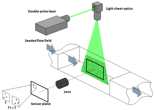
PIV is an imaging technique to measure the velocity distribution within the plane defined by the laser light sheet. It is widely used in various fluid dynamic researches.
Optical setup
PIV is one of the so-called Time of Flight (TOF) measurement techniques. The basic principle of the PIV is that a laser light sheet is used to illuminate the flow field which is seeded with small particles to visualize a flow to be measured. A double pulse YAG laser and a double shutter camera are synchronized to record two particle images with very short time separation, typically less than 100 us.

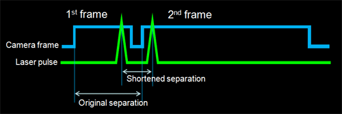
Frame straddling
PIV requires two particle images with very short time separation typically less than 100 micro seconds. The frame straddling technique enables to record two images with time separation of down to 100 nanoseconds. A double pulse laser and a double shutter camera are synchronized by the timing controller. Since the double pulse laser has two laser heads which can be operated independently, actual limitation is the length of dead time between two frames of the double shutter camera.
Displacement and velocity evaluation
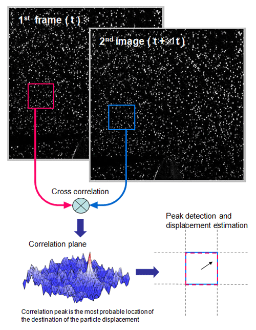
Once the images are successfully recorded, the next step is the PIV analysis. The images are divided into small search areas, typically 32 x 32 pixels. These small search areas are called interrogation windows. The cross correlation is applied to these interrogation windows for both two images to obtain the correlation plane for each interrogation window. The location of the interrogation windows in both images are same (In the Standard FFT cross correlation, the interrogation windows are shifted in the advanced algorithms).
Then the peak detection and displacement evaluation are applied to obtain the dominant displacement in each interrogation window. As the size of a pixel in flow and the time separation between two images are known, the velocity can be calculated. The size of a pixel in flow is determined by the simple velocity calibration.
2D-PIV and Stereo 3D-PIV Data format
Both PIV results are the same flow; Free jet from the 100 mm x 100 mm square nozzle. The dashed line on the 2D-PIV data corresponds to the measurement plane of the Stereo 3D-PIV.
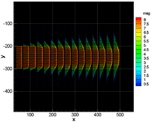
2D2C (2 Dimensions 2 Components) |
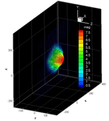
2D3C (2 Dimensions 3 Components) |
Related Information
PIV ( Particle Image Velocimetry ) | Overview & Principle
https://www.seika-di.com/en/measurement/principle_of_piv.html
PIV system components
https://www.seika-di.com/en/measurement/principle_of_piv/piv_system_compnents_en.html
